

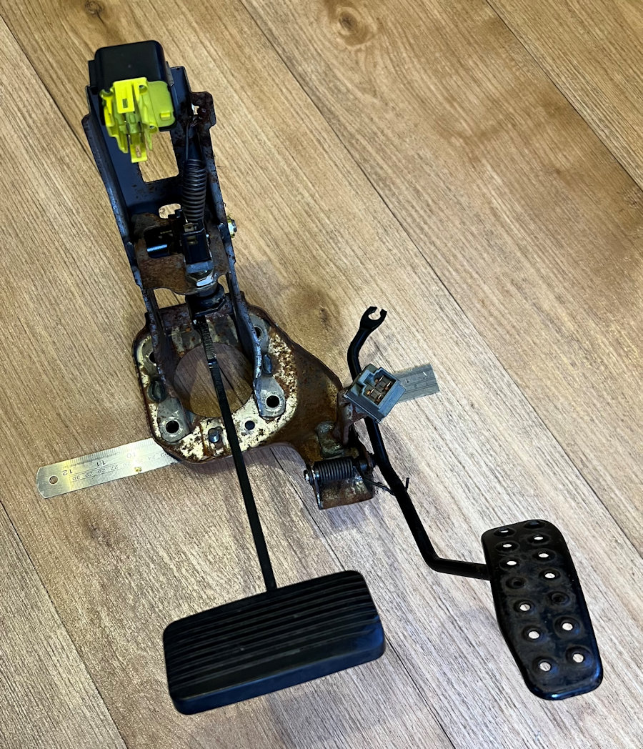
The Eunos Roadster we are converting to our MX-5e was an automatic, so it came with a pedal box with just an accelerator and brake pedal. Whilst this is helpful, we are fitting a iBooster and this has a slightly different pattern for the mounting holes. It also has some welded spacers on the back of the pedal box mounting plate, which make it really difficult to modify. We also need a throttle/accelerator pedal that interfaces to the Vehicle Control Unit (VCU), rather than a cable driven throttle body.

The MX-5 pedal box is fairly well made but it is quite heavy (2060g) and features some things that we no longer require, such as a spring return on the brake pedal. The actual position of the pedals and pivot points is right for our MX-5e needs though, so we can reuse some parts.
The throttle pedal part of this pedal box is notorious for cracking and we have already replaced the one in Yoko, which had already been repaired/welded. We are very keen to remove this inherent weakness.
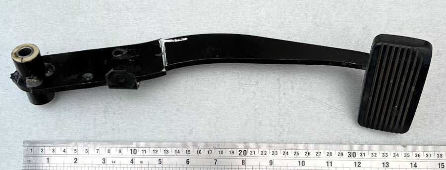
The MX-5 brake pedal is a solid piece of steel 6mm thick and it weighs 770g on its own. The pedal pivots on a 10mm bolt with nylon bushes on a clamped tube (55mm long). This works well but we would ideally use proper bearings.

To check the positioning and function of the brake pedals, we are designing and 3D printing the components of the pedal box. We started with a brake box mounting plate, which matched the bolt mounting holes of the iBooster. The 20mm spacers currently welded to the MX-5 pedal box seem to be about right. We measured the distance from the mounting face to the centre of the clevis pivot and it was about 125mm in both cases.
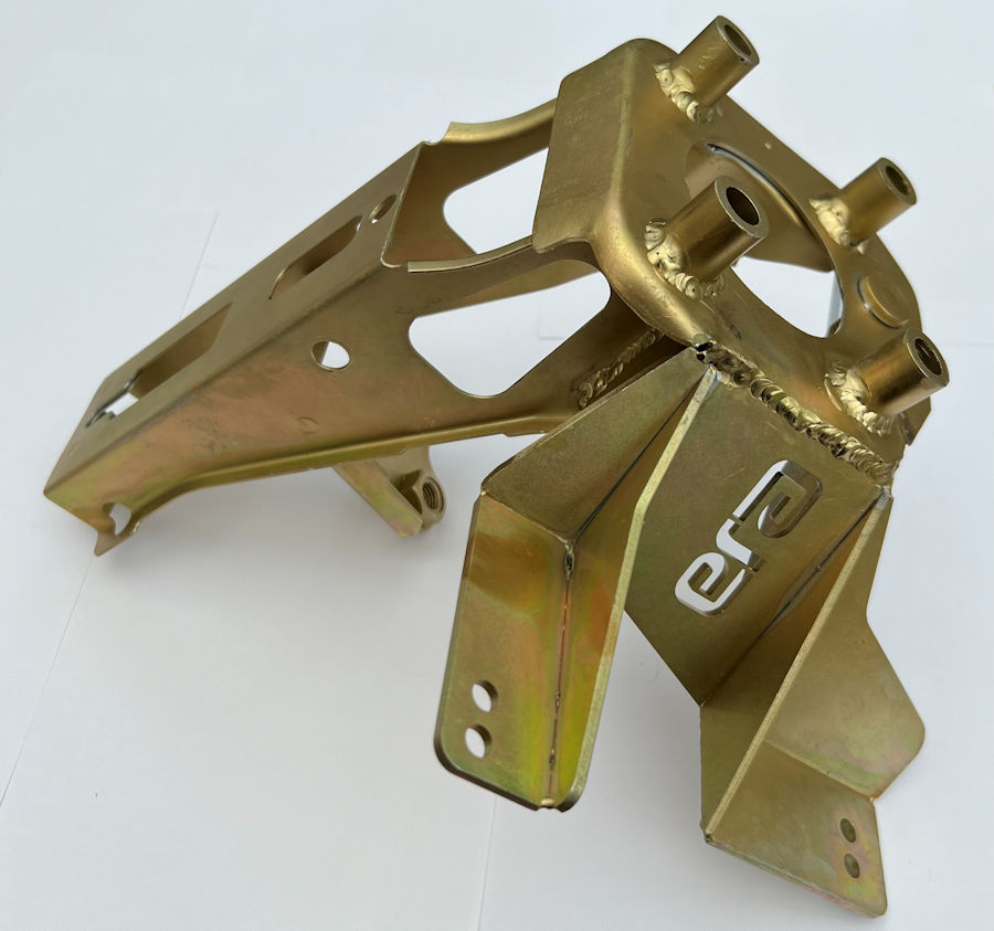
Our original plan was to use the original throttle pedal but, after having had a chat with Doug at G19 Engineering, we decided to use the Mazda MX-5 NC/mk3 electronic throttle pedal. Doug sells a product that strengthens the existing pedal box in MX-5s provides a stronger mounting point for this throttle pedal. He offered to help make a custom version to fit our MX-5e. The mounting spacers have been moved and re-welded back on, in the correct location for the iBooster. He has added a much stronger mount for the throttle pedal, with two mounting positions, to change the gap between the pedals. The pedal box has also been zinc plated.
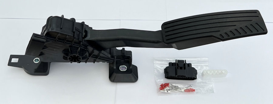
Doug also supplied a second-hand mk 3 throttle pedal and a new matching connector. This makes our life a lot simpler in terms of the engineering and wiring required to get the brake pedal and throttle pedal working as planned. The throttle pedal will interface directly to the Vehicle Control Unit (VCU).
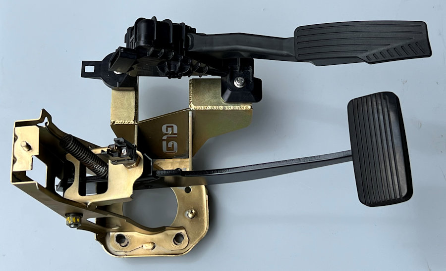
This is the pedal box all back together with all of it having been refurbished and the brake pedal resprayed. We have fitted the brake pedal return spring for now as it holds the brake pedal in place but, it is not required in our MX-5e application.
The brake switch is required and is connected to the Vehicle Control Unit (VCU).
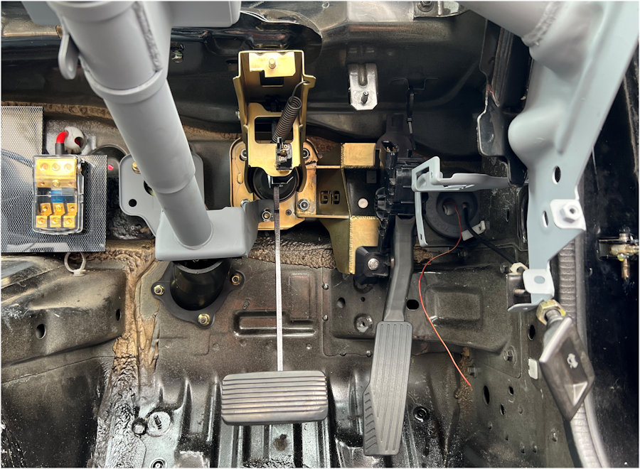
The modified pedal box fits back into the original space perfectly and bolts to the iBooster easily too.

The mk3/NC Mazda MX-5/Miata throttle pedal is technically called the 'Accelerator Pedal Position Sensor' or APP sensor. From our research we can see that there are two potentiometers in the APP sensor, exposed via the 6 pins on the connector. Pins A, B & C are sensor #2 and pins D, E & F are sensor #1. Our research suggests the following:
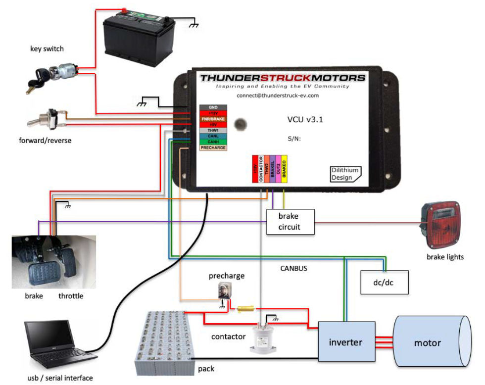
Two-wiper throttles are used as a safety feature to prevent a single point of failure. The Vehicle Control Unit (VCU) that we are using in the MX-5e supports this and has two inputs: THW1 & THW2. By default, the VCU assumes that a single wiper throttle and only THW1 is used. If configured, the VCU firmware requires that the two wipers track each other and provide consistent readings. A dual wiper throttle is configured with the command set thtype dhall. Both throttle outputs have configured high and low settings (thw1off, thw1max, thw2off, thw2max), which determine the limit values for each wiper. The VCU provides 5V power to the throttle and both THW1 and THW2 expect a 0V to 5V input.
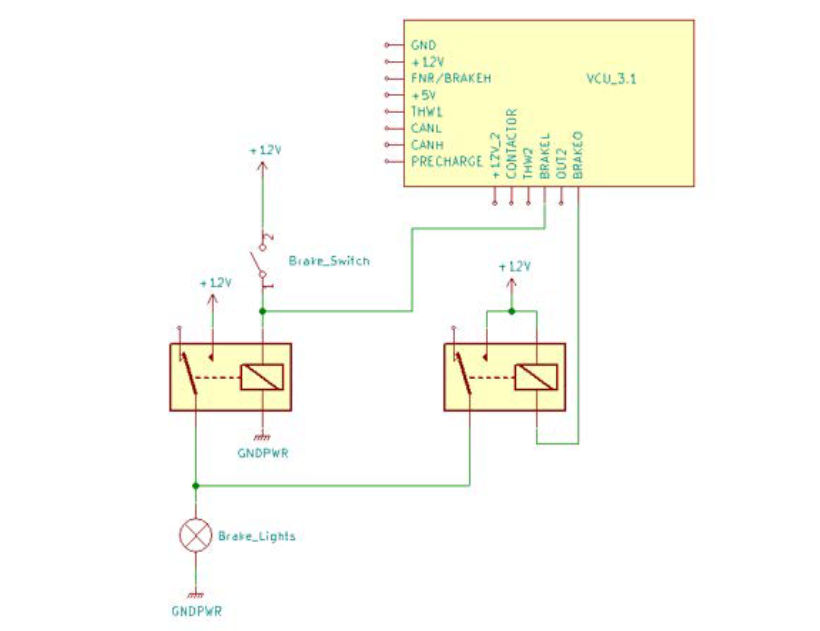
The existing brake pedal switch is connected to the Vehicle Control Unit (VCU), which uses the signal to control the regenerative braking.
| Pin | Function | MX-5 Loom | MX-5e Loom | Notes |
| A | 5V | red/black | red | From VCU |
| B | GND | brown | black | To dash GND |
| C | THW2 | white | orange | Sensor #2 |
| D | 5V | yellow/blue | red | Connected to A |
| E | GND | grey | black | Connected to B |
| F | THW1 | green/red | grey | Sensor #1 |
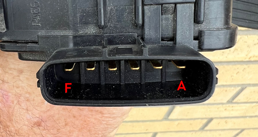
This is the connector socket on the mk3 MX-5 throttle pedal. Using the above pin designations, we tested both sensors in the pedal with 5.00V dc. The output on pin F (sensor #1) varied from 1.6V to 3.9V. The output on pin C (sensor #2) varied from 1.0V to 3.4V. These figures exactly match those suggested by our research.
measure command is a diagnostic function that shows the actual values read at a VCU input. This command
may be used to verify the throttle wiring and to measure the actual range seen at an input. The measure command can be used with thw1, thw2, brake, or brakel. It will repeatedly show the requested current input value and can be stopped by pressing any key.vcu> measure thw1
thw1= 0.44V
thw1= 0.44V
thw1= 0.44V
thw1= 0.44V