

This project is documenting all the 12V (low voltage) wiring we are installing in our MX-5e. In October 2023, we made the decision to completely empty the engine bay and respray it. As part of this process we used bolt croppers to cut the wiring loom at the two points where it passes through the bulkhead, simply because so much of the wiring is ICE related and redundant to our EV conversion. It is just going to be simpler to rewire the whole car from scratch and document it along the way. This is also going to allow us to install a much simpler and lighter wiring loom.
When stripping out the loom, we have tried to keep the wires to the connectors as long as possible to avoid the need to splice longer wires on if at all possible. We have to remove all of the wiring tape and sleeving to achieve this.

Having taken all the wiring from the engine bay and stripped it right down, we were left with the 4kg of redundant wiring shown here. The only bits we have kept are the connectors for the lights, pop-ups, washer bottle and windscreen wipers. When stripping the loom, we tried to keep the connector wiring as long as possible. There are some internal junction points which limits the lengths in places though.

To save a huge amount of weight, it makes sense to move the 12V battery into the engine bay (it is located in the boot in the Eunos/MX-5). This removes a huge amount of thick battery wiring that runs the whole length of the car and weighs more than the battery itself. It means we can use much shorter lengths of higher current wiring to things like the front lights, cooling fan, cooling pump, iBooster, etc.
Because an EV battery is not used to start a petrol engine, it can be much smaller and lighter. This will also make it much easier to find a suitable location for it. Rob used a Yuasa YTX12-BS 10Ah motorbike battery in his Fisher Fury R1 and we plan to use the same battery in the MX-5e too. The dimensions are 150mm (w) × 87mm (d) × 130mm (h) and it weighs 4.2Kg.
Assuming a worst case constant load of 20mA, an 10Ah battery should last 500 hours or 20 days. Given all the other 12V battery protection mechanisms planned, we think this should be fine.

The battery connects into this ANL fuse junction box and this has three (currently) 60A fuses to feed the ignition switch, the unswitched fuse box and the dc-dc converter. This weighs 322g.

We have prototyped a mounting plate under the dash (mostly behind the heater matrix) on which we have mounted the main fuses (on the right, so that they remain accessible). This results in a super short set of battery cables to save weight. The positive lead is just 35cm long and the negative lead is just 30cm long.

We are building custom fuse boxes for the MX-5e using these 8-way fuse holders and these will sit in the engine bay and under the dash. It is just a lot simpler than trying to cobble something together with the existing fuse boxes (there are two on the Eunos Roadster) and the old wiring loom (which is also being replaced).

We are reusing this mount for the old fuse box as it is nicely situated in the engine bay.
The relays in the engine bay to minimise wiring lengths:
There are two changeover relays mounted on the headlight units, to control the pop-up headlight mechanism.
The two relays for the heated seats are mounted under the dash, again to minimise the wiring length.
Both inside the engine bay and the cabin, it is often challenging to reuse the existing mounting points and brackets in most cases. To make our life easier, we are mounting flat plates in various locations that can be drilled to suit our chosen components. This approach reuses exisitng mounting holes and bolts, so we don't have to drill any new ones in the chassis or bodywork. This makes life easier when we register the MX-5e as an EV.

Our original plan for the MX-5e was to have keyless entry but, it just makes much more sense to leave the ignition/steering lock in place and use a key to start the EV. From an MOT/IVA test perspective this just makes life a lot easier as it provides a physical steering wheel lock. The key is used to open the doors (if not using the central/remote locking) and also the boot (if not using the internal boot release). It also means we can easily protect the 12V battery by disconnecting components via the ignition switch. The Driver Control Unit (DCU) will still provide automatic driver profile and deliver a personalised experience.
The ignition switch has four positions: LOCK/OFF, ACC, ON, START (momentary) and a 6-way connector:
When we tested the ignition switch, we found some intemittent connections and ended up taking the electric module apart to clean it. It has loads of tiny springs inside and two switch plates that have to be refitted correctly.

In the Eunos Roadster, the column switch for the lights carries high current to the headlight bulbs. In our MX-5e this will not be the case (side lights aside) and the light switches will simply control relays.

Our original plan was to swap out the existing column switch module and to fit modern replacements. At the same time, we planned to swap the indicators to the left side and the lights switches to the right side. We have now decided to leave the existing column switch module in place until after we register the car as an EV with the DVLA. We are wiring it up with this change in mind though.
This image shows the back of the switch module in the Eunos Roadster, which has the light controls on the right-hand side and the washer/wiper controls on the left-hand side. The module has three main connectors with 6.3mm spade terminals for the lights + horn, indicators and the washer + wipers. There is also a 4th 2-way connector at the bottom of the module.
The horn described in detail later.
Although this is a 6-way connector, only 3 terminals are used. The wiring is described in detail later.
The washers/wipers are described in detail later.

This 2-pin connector with 6.3mm spade terminals has two wires: white/red and red/blue, which power the left and right side lights and headlights.
These were high current wires as they directly switched the side lights and headlight power in the Eunos Roadster. In the MX-5e they will only power the side lights directly and the headlights are controlled via relays, so we are changing the pins and the wires. These two wires will also be linked at the connector.

We are replacing the existing switches and blanks, so that we can fit more switches into the same space.

Our eventual plan is to replace these and use an on-off-on toggle switch on the left for the lights (off/side/main). The middle one will be fitted with two round, momentary push switches to wink the pop-up headlights. The right will have two round, latching push switches, an orange one for the fog lights and a green one for the pedestrian warning system. To achieve this we have designed and 3D printed new switch mounts.
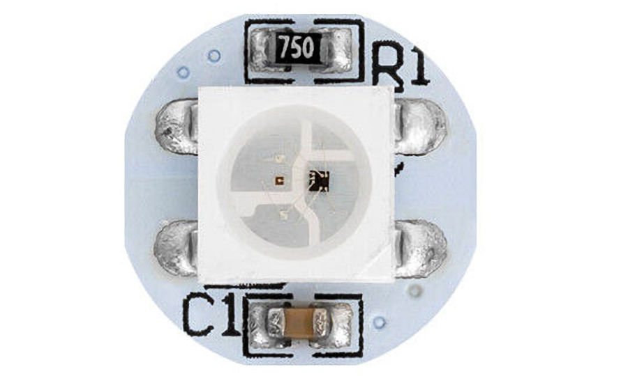
The Driver Control Unit (DCU) controls the interior and ambient lighting in the MX-5e cabin and it is personalised to each driver profile. This includes the two interior lights mounted on the dash and the footwell lighting.

The Eunos has a cigarette socket on the dash and we plan to reuse this. In parallel, we will also fit a locking charge socket that can connected to our Optimate 6 smart battery charger and conditioner. These will be directly connected to the battery via a 10A fuse. This approach worked really well in Rob's Fisher Fury R1.

There is no alternator in an EV, so a dc-dc converter is used to run the 12V systems and charge the 12V battery from our 400V battery. We are using the Elcon 1000W dc-dc converter from Fellten. The DCDC206-454 model accepts an input voltage between 206V and 454V and can supply up to 85A at 14V dc.
A fuse is required on both the HV and LV side. The manual says to use a 100A fuse on the 12V side but, we are using a 60A fuse initially. Connecting the dc-dc converter is really easy and the use of the CAN Bus is optional as it features simple 12V control lines and signal lines. We do plan to use the CAN Bus features.

Our MX-5e came with a remote/central locking system installed but, we are replacing the receiver unit with something more modern, more secure and with new key fobs.
It will be wired in properly with its own 15A fuse in case we want to disconnect it, to further protect the 12V battery. The doors can still be unlocked with a key and indicator that the system is disabled will be that the blue dash LED is not flashing when the car is locked.
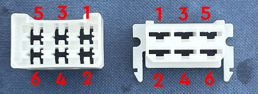
The doors use 6-way connectors, with the female connector on the cabin side:

The cooling system is covered as a separate MX-5e cooling project but, the electrical elements of this are detailed here.
The power to the cooling fan and the fan control switch/sensor is unswitched and via a 10A fuse. The fan is powered via a relay as it is rated at 80W. It is fused and on a non-switched connection to the 12V battery, so that it can continue to run after the ignition is switched off. The fan relay is activated by an 85°C temperature sensor/switch, which pulls one side of the relay coil to ground.
A fan 'power sense' wire runs to a visual indicator on the dash, to show when the fan is in operation.

Each door has a 4-way spade connector that feeds it via a flexible rubber moulding. The two thicker wires are for the electric windows and the two thinner wires are for the speakers.

We are replacing these with new 6-way spade connectors to support the speaker wires, central locking and the electric windows. In addition, we are adding a much smaller 3-way connector for the ambient lighting in the doors.

We are using these 6-way connectors for both doors. They carry the connections for the speakers, electric windows and central locking.

The electric window connectors LH[81] and RH[82] have wires behind the tombstone and under the centre console, to the window switches. The centre console has a 6-way 6.3mm spade connector to the electric window switches [80]. The black wire runs to ground and the black & white wire provides power via a 30A fuse.
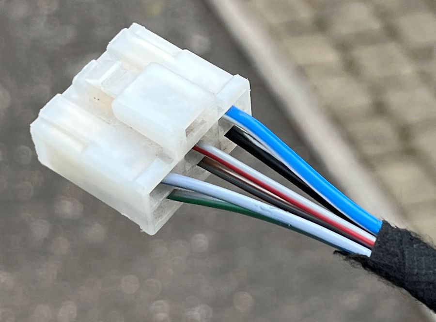
We have reused the connector at the centre console end but, have fitted new terminals and wires to the door connectors. The 2mm² power cable from the fuse box is blue/white.
We have swapped the original wires at the right connector: green -> slate/brown & green/red -> slate/red.
We have swapped the original wires at the left connector: red/black -> slate/blue & red/gree -> slate/green.
The centre console also has wiring via a 2-way connector for an interior light on the ash tray. This is not going to be used but, we are running power to the smartphone charger on the centre console.

The HVAC controls on the tombstone are backlit via a 2-wire connection linked to the side lights. The connections to the heater matrix are purely via cables and the heater previously worked on the principle that heat exchanger was always "on" when the engine was up to temperature. The temperature control simply variably mixes the flow of air that comes from the cold and hot side.
In the MX-5e we are going to have to physically turn the PTC heater on when required. Because we have removed the air conditioning system, the 'A/C' button can be reused to enable the PTC heater (via a contactor) but, only when the ignition is on. We can't simply turn the PTC heater on when the fan is in use because the fan will mostly be used in the summer months to move cool air into/around the cabin.

There is a bit of the wiring loom that connects the cabin 'heater blower' [18] (fan unit) to the 'heater blower switch' [17] mounted on the tombstone. We left this alone and are reusing it. The fan unit also has a seperate connector that delivers power to it. This is fed via the cabin fusebox [6] (30A fuse) and this gets power from the ignition switch [5] (connected via a 60A fuse).

The plan is to wire the PTC heater up (via a contactor) to the A/C button on the heating controls. In practice this is not as simple as it looks, as the Eunos Roadster is wired differently to the wiring diagrams shown. We are going to have to modify the wires soldered to the switch pins and re-route them and expose them on some of the spare wires that use the connector (blue/orange + green/red). There is also a blue indicator light that can be used to show when the PTC heater is on.
Aside from the central locking, the only other thing connected to the 12V battery when the EV is 'off' is the Driver Control Unit (DCU) and this controls power to the Vehicle Control Unit (VCU).

The MX-5e came with twin, two-tone Misuba 'Alpha Horn' horns which are plenty loud enough, so we cleaned and refurbished them so they could be reused. When it came to refitting them though, they were not a nice fit. We have replace them will a pair of Hella S90 horns.
Each one is rated at 12V 4A, so we are using a relay to switch power to them via a 10A fuse. The horn connections are not polarised and one side is grounded locally to the chassis. The steering wheel horn button activates the horn relay by taking the low side of the coil to ground. The relay switches the 12V power to the horns.
The horns are earthed locally in the engine bay using 1mm² (16.5A) cable and fed via a 1mm² green/red wire from the relay and a 1mm² green/white wire from the fuse box to the relay. The wire from the horn switch to the horn relay is 1.0mm² green/orange cable on the 6-way connector to the main light switch. This pulls the relay coil to ground.

The pedestrian sounder/buzzer beeps loudly and has been made intermittent by using a 3-pin CF14 flasher unit. It uses the same fuse as the horns and is controlled by a latching switch on the dash. It is 12V and uses just 0.3A and weighs just 28g.
It has two 6.3mm spade terminals on the back, one male (+ve) and one female (-ve). The cable used is yellow/red and 0.5mm².
The MX-5 wiring diagram simply doesn't always match the wiring found in our Eunos Roadster. We are also simplifying the wiring of our MX-5e and also adding the ability to wink with the pop-up headlights. The main things we are doing are:

We have reverse engineered the wiring of the pop-up headlights (headlight retraction) on our Eunos Roadster, to put each side under smarter control. The existing Eunos wiring is a lot more complicated than it needs to be and we also want to be able to operate the pop-up actuators independently, so that our MX-5e can 'wink'. A few things we have noted:
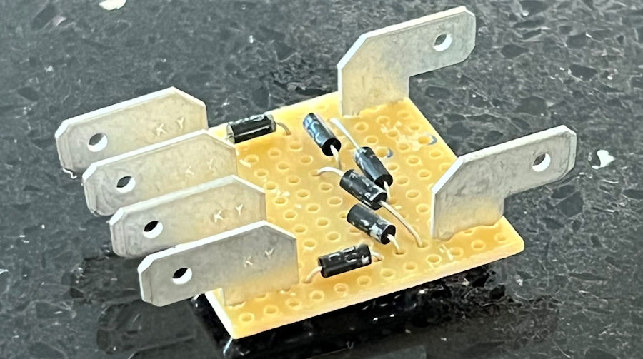
We are wiring the pop-up headlights independently, each with it's own 15A fuse and changeover relay (to avoid conflicting up/down requests. To enable independent control via the headlight switch, headlight flash switch, the tombstone 'pop up' switch and our own 'wink' switches, we are using 1N4007 diodes to implement the basic control logic (multiple input OR gate) required. This approach means these relays are enabled when the headlights are on.

The 6-way connectors to each headlight actuator on our car has five wires: +12V (brown), GND (black), error/indicator (green), up signal (red/yellow) and down signal (white/red). The error/indicator wire goes high when the actuator is in motion or an issue arises. This would normally light up an indicator on the dash.
To keep the wiring simpler/shorter, we are locating a changeover relay next to each headlight unit and swapping out the existing connectors. Just to make things more interesting, the colour coding of the wires changes on the other side of the connector.
| Function | Schematic Colour | Actual Colour | Connector Colour To Unit |
| Up | Red/Yellow | Red/Yellow | Red |
| Down | Red/White | Red/Green | Yellow |
| Ground | Black | Black | Black + White/Black |
| Power | Brown | Brown | White/Red |
| Error | Green/Blue | Green/Blue | Green |
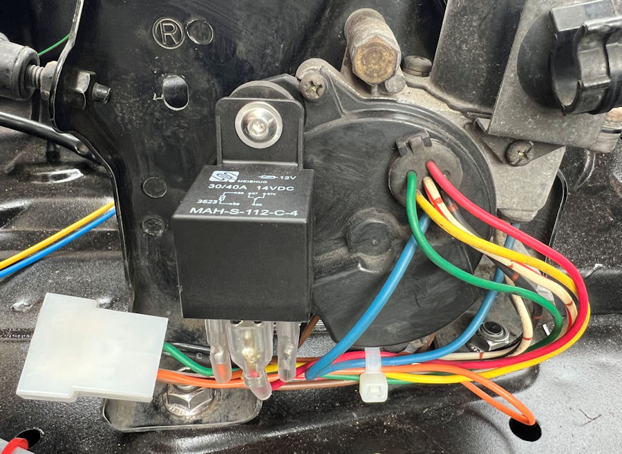
The use of a change-over relay local to the headlight retraction unit simplifies the wiring significantly and provides independent left and right control. These wires will be wrapped after testing.
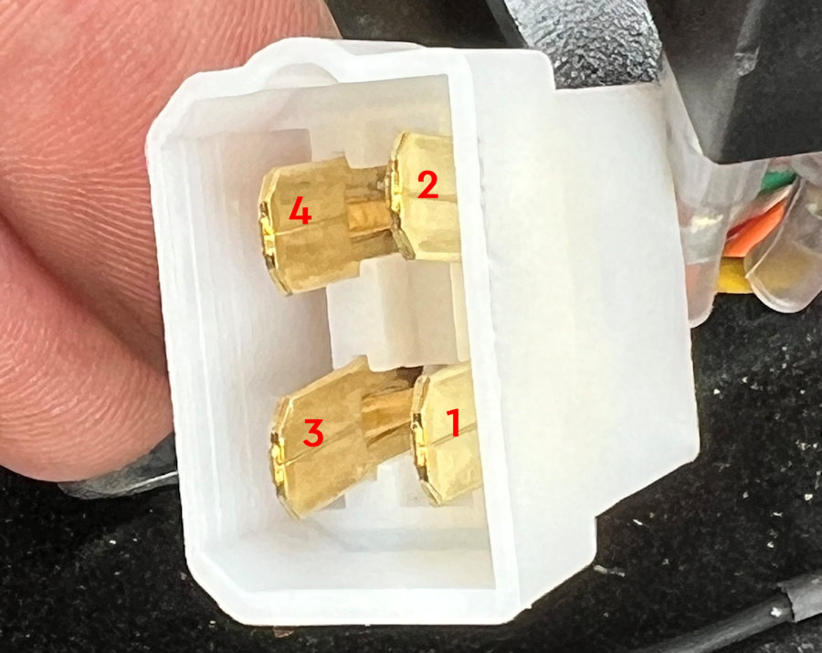
Our 4-pin connector pins are:

The wiring to the headlights is a little bit odd in the Eunos Roadster. It uses sealed halogen 50W/50W units with an H4 connector on the back. The earth wire (black) and the low beam (red/black) are both 1mm², with the high beam being 2mm² (red/white). I guess the earth wire is shorter and can causes less of a voltage drop.
The headlight power for the low beam and high beam goes through two relays and these are controlled via the column light switch. The control wires to the relays are also fed to the pop-up headlight module, to ensure they come up when the headlights are on or flashed.

Whilst we refurbish the pop-up headlights, it makes a lot of sense to replace the H4 bulb connectors, so we can fit 2mm² wiring all the way to the bulbs.
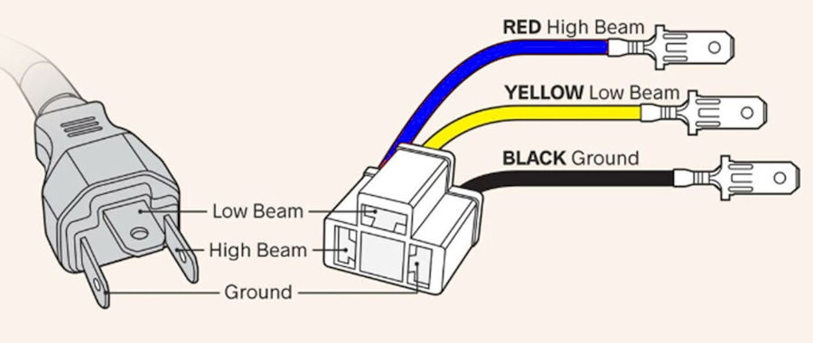
Modern headlights use H4 bulbs, which are rated at 60W/55WW, so we can expect both sides to use 120W or 10A at 12V. For this reason, the high current elements are using 2mm² cable rated at 25A. This ensures they are no significant voltage drops and we use relays to keep the high-current cabling as short as possible. High beam is blue, low beam is yellow, high beam control is blue (0.5mm²) and low beam control is yellow (0.5mm²).

We are using a CF14 JL-02 flasher unit because this gives a constant flash rate regardless of the indicator bulb/LED load present. This one also makes a suitable noise in operation, though we could add an additional 12V buzzer if required. It will be located under the dash.
The existing hazard switch is reused to operate the indicators on both sides.

The CF4 module has no obvious mounting points, so we have 3D printed our own, to allow it to be bolted to our mounting plates. We glue this mount to the CF14 module using Araldite. This approach makes it easy to swap them out, should the need ever arise.
For each side of the car, there are a number of indicator wires that come together (front, rear, visual indicators, switch, etc.) and so we have two junction points.
The side lights are relatively low power and will eventually be LED, so 1.0mm²/11A cabling is used and this is orange. They also power the rear number plate lighting.
We are not actually fitting DLRs to the MX-5e initially but, we are running 0.5mm²/11A white cables to enable us to add them later if required. We will just use the side lights in the meantime.
The Eunos Roadster rear lights are wired to two main connectors that attached to the rear light clusters. Other wiring runs to the high-level brake light and after-market fog light on our MX-5e. The colour coding is:
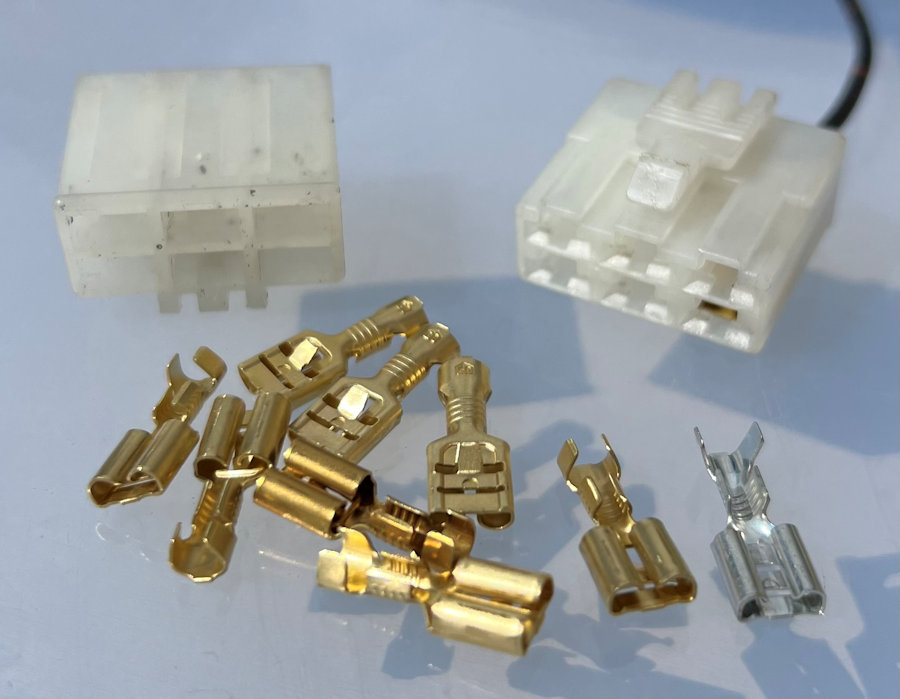
The rear light cluster connectors are bespoke to the MX-5 NA but, with the right tool the terminals can be removed from the matching plug and new 6.3mm spade terminals crimped and re-fitted.
These old style connectors do not using locking tabs on the underside of the crimp terminal. The terminal is held in place by the curled prongs and these need to be big enough to hold the terminal in place. The silver terminal pictured here will not work as there is too big a gap between the curled prongs.
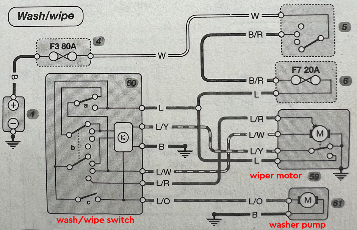
The wiring of the windscreen wipers and washer is simply. We have reused the connector at the steering column and fitted new terminals and wiring.

The wiper motor is being reused. It has its own local ground connection to the chassis. The connector has four wires: blue/red, blue/white, blue/yellow and blue. These connect directly to the steering wheel stalk/switch.

We are reusing the windscreen washer bottle and pump as it is very light (it weighs 1040g) and fits perfectly in place as it was designed. Both the wipers and washer bottle pump are are fed via the ignition switch and a 20A fuse in the MX-5, with no relays used. This means they can't be left on when you leave the car.
The washer bottle pump has a female connector with two wires to the pump motor (blue/red and blue/yellow). The male connector we are reusing has two wires with the blue/orange (positive) connected to the blue/yellow. The other wire is blue (black in our wiring diagram) and goes to ground.
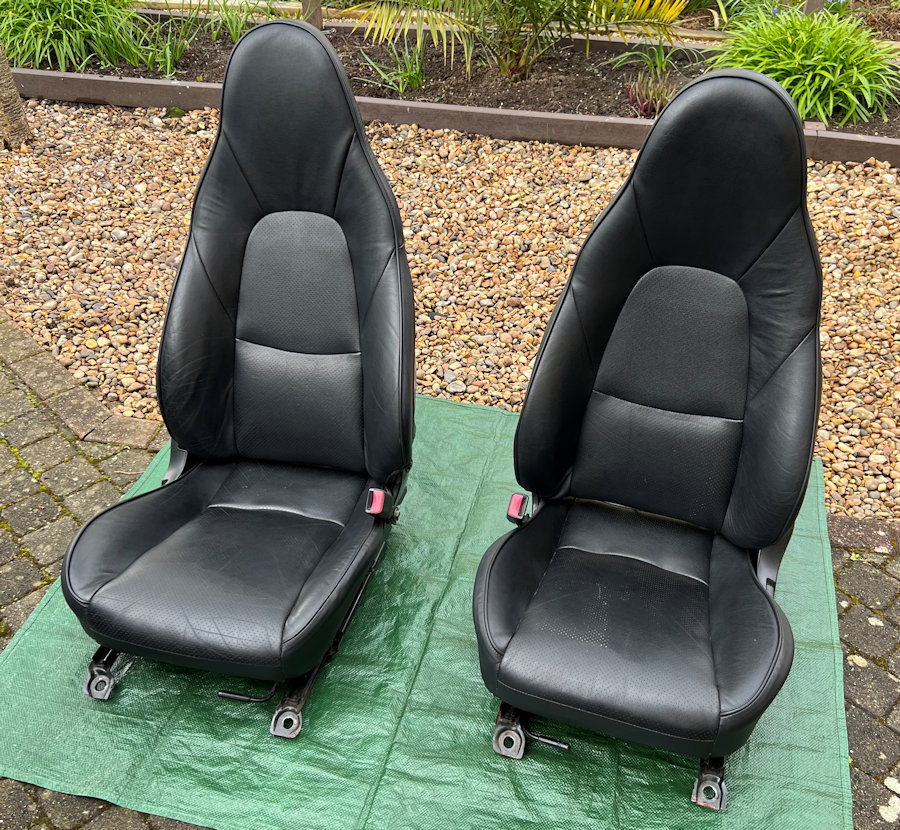
We have fitted a pair of MX-5 mk 2.5 black leather heated seats and these have in-built heaters. We measured the heater resistance at 2.4Ω, so they are 60W at 12V dc (70W at 13V dc). Each heated seat takes about 5A, so we are using a 15A fuse to power them both via 2mm² cable. These are binary heaters (on or off), with no temperature settings. There is an in-built thermostat in the seat though, to limit the temperature reached.

Underneath each seat is some wiring and a connector. The driver's seat is pictured here and it has a 4-pin connector (shown below).
The passenger seat is slightly different and has a 5-pin connector.

The 4-pin connector on the driver's seat has red + black wires for the two heating elements (seat + seat back) and blue/red + white wires (normally closed) for the seat belt warning light. The seat belt warning light is powered via this connector and the ignition switch and when the belt is plugged in, the circuit is broken.
The passenger seat also uses the red + black wires for the heating elements but it has three other wires. These are not linked to the seat belt and we currently have no plans to use them.
On both seats we are cutting off these connectors and using standard 4-way, 6.3mm blade terminal connectors.

We are using the genuine dual switch for the heated seats. The actual switch is plugged into the larger module pictured here.
These switches have illumination and are not capable of switching the currents involved, so we are using a relay for each seat.
The majority of the visual indicator lights use a 12V dc signal but, a few are 5V dc and some are pulled to ground.
There is a permanent power feed via the passenger footwell fuse box (Yellow 4mm2) and this feeds the radio and sub-woofer.
There are also two fuses in the Cabin Fuse Box 1 that are switched via the ACC position on the ignition switch. These feed the radio and touch screen + dashcam and wireless phone charger.
We have wired this in using two connectors, to keep the speakers seperate from the power and other functions. An 8-way connector is used for the FR + FR + RL + RR speakers. A 6-way connector is used for GND, permanent power, switched power, remote control of sub-woofer, display dimmer and audio interrupt.
The sub-woofer has a power enable line (Blue), which is connected to the ignition switch ACC line via a fuse and via a Black/White cable.
The sub-woofer also has a remote control unit that runs from the device to the front of the car.