
Open-Source Sports Electric Vehicle (OSSEV®)

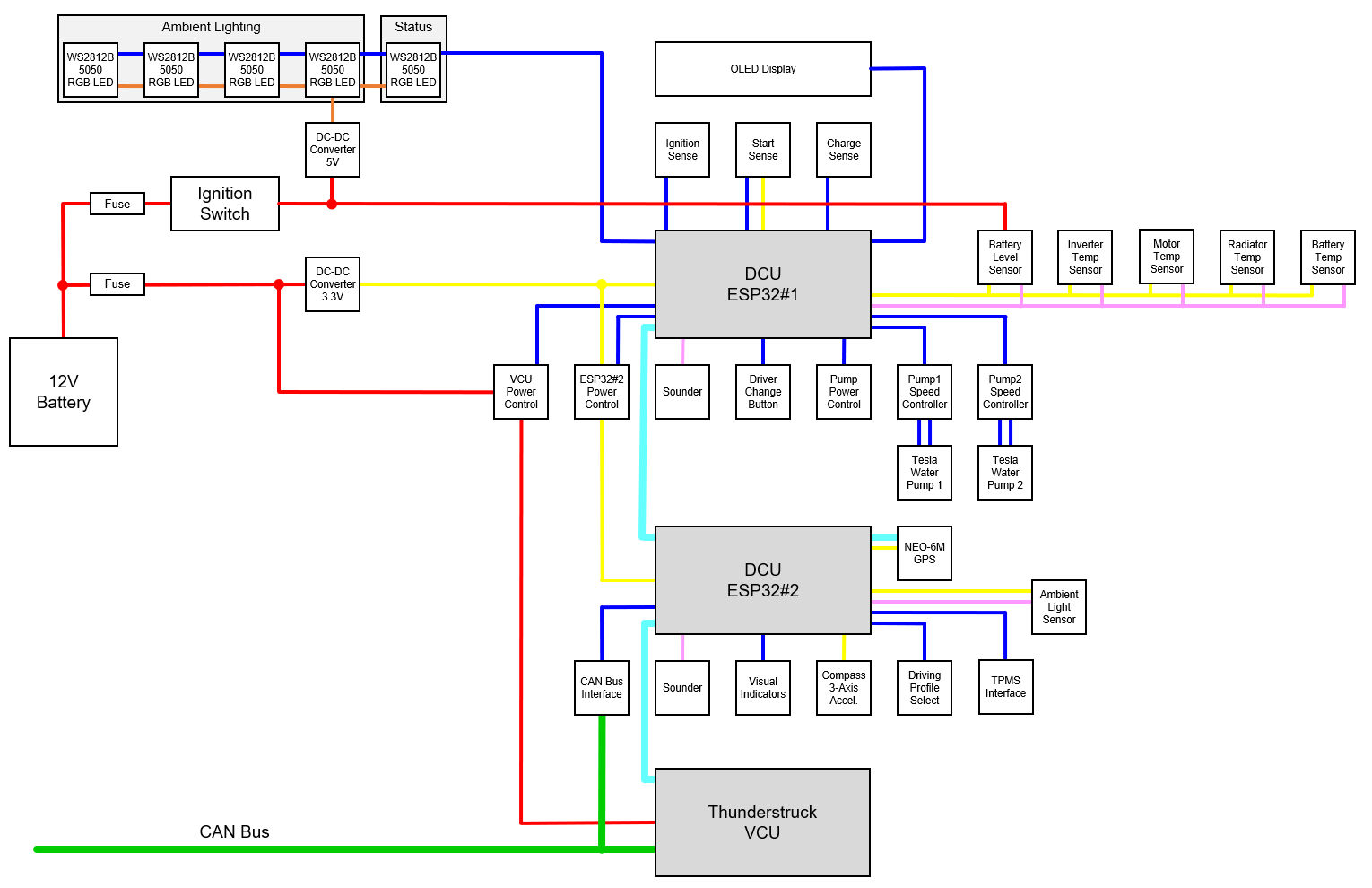
The Driver Control Unit (DCU) is the hardware and software providing the best possible driver experience for the OSSEV®. It implements the Intelligent Security & Personalisation (ISP) feature and manages both the and driving profile. It is also responsible for all feedback to the driver via the instruments and controls and Head Up Display (HUD).
The DCU is responsible for enabling the Vehicle Control Unit (VCU), which enables the OSSEV® to be driven.
This diagram shows the main components and the power sources (yellow = 3.3V, orange = 5V, red = 12V). Serial communications are shown in cyan. Digital IO is shown in blue and analogue/PWM in pink. The CAN Bus is shown in green.
Our DCU uses two processors:
The DCU supports the following features:
Before going into the design detail, it is worth describing the user experience we are aiming for. This is based on the user experience we think is possible in our MX-5e and it uses the existing ignition/steering lock and key.
The key switch in the MX-5e has an 'ACC' position and this supplies power to the entertainments system. It does not enable the DCU in this position.
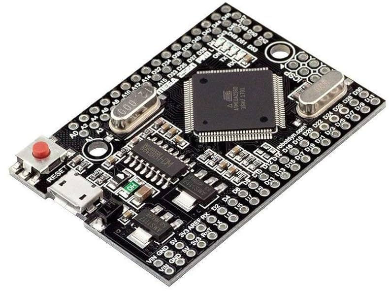
We were originally testing using the Arduino processor Mega 2560 Pro because it has an amazing amount of processing power, analogue and digital IO capability is a tiny package. It doesn't support Wi-Fi or BLE though. We are currently using this for DCU2.
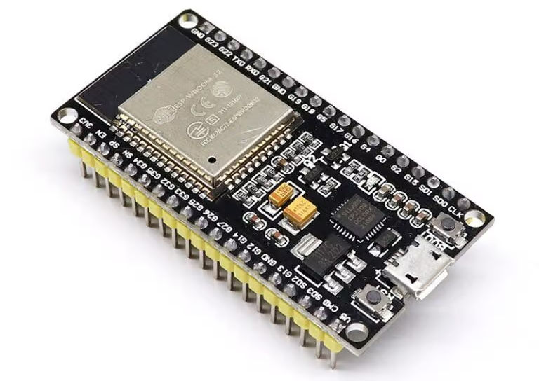
We are using an ESP32 processor it is permanently connected to the 12V battery and therefore needs to use minimal power. It does this by using a very low power dc-dc converter to deliver the required 3.3V dc from the 12V battery. In deep sleep the total DCU load on the 12V battery is <2mA. Another advantage of these processors is that the start up time is less than one second.
The ESP32 has the Bluetooth Low Energy (BLE) capability required to detect key tags and these are used to help select the driver profile and help deliver a personalised driving experience. The ESP32 has Wi-Fi connectivity and connects to the home network to report data back to our smart home.
When the ignition is on, the ESP32 is 'awake' and performing a number of functions. It monitors the ignition key and enables and disables sensors and other hardware as required.
When the ignition is off, the ESP32 processor spends most of its time in 'deep sleep' mode and uses virtually no power. At regular intervals (typically every 6 hours), the ESP32 awakes from its deep sleep and performs a number of checks by enabling sensors and other bits of hardware. It is wake for less than 30 seconds.

We use dc-dc converters to accurately generate both 3.3V and 5.0V dc as these are both the power supply and the voltage references for analogue to digital conversions. These things are cheap and readily available on sites like eBay. Having used them in our smart home for 20+ years, we know they are incredibly reliable.
We are using a second processor that is powered via DCU1 to:
DCU1 and DCU2 communicate with each other via serial port and send comma separated name/value pairs over the serial link.
For the initial development, we are using an Arduino Mega 2560. These processors are bullet proof, have loads of IO capability and lots on memory. Rob has used them in his smart home and other connected vehicles for 10+ years.
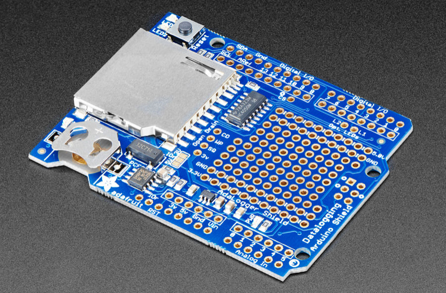
DCU2 performs data logging for diagnostics and the same data storage technology is also used to store driver profile data.
We are using this Adafruit data logging shield to store data on an SD card.
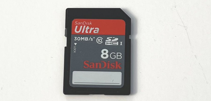
For initial testing we are using this 8GB SDHC card.
The data logging shield features a Real-Time Clock (RTC) with battery backup. This is really useful as it allows all data logging to be accurately time-stamped before the GPS module acquires a signal and is able to re-synchronise the time held by the RTC.
We are not going to go into the detail of this here. Rob has documented this in great detail on his smart home website.
The 12V battery voltage will vary from around 12.0V to as much as 15.0V. You can't simply connect the battery to an analogue input, so we use a voltage divider. Putting 12V across a resistance such as our voltage divider will add a 'phantom load' and start to drain the battery, so we have to ensure the voltage divider has a very high resistance, to make this additional load negligible.
We have a 3.3V maximum input on our analogue pin, then we need to divide the 16.0V (worst case) by about 4.85, to ensure we stay within the 3.3V limit. If we use a 100KΩ resistor in series with a 20KΩ potentiometer, then we are adding a negligible load to the 12V battery (about 0.1mA).
The analogue input is 12-bit and reads 4096 at 3.3V. By adjusting the potentiometer, we calibrate it to read 3072 with a 12.00V input (i.e. 4096 at 16.0V), meaning each bit read represents 0.004V. This is way more resolution and implied accuracy than we actually need.
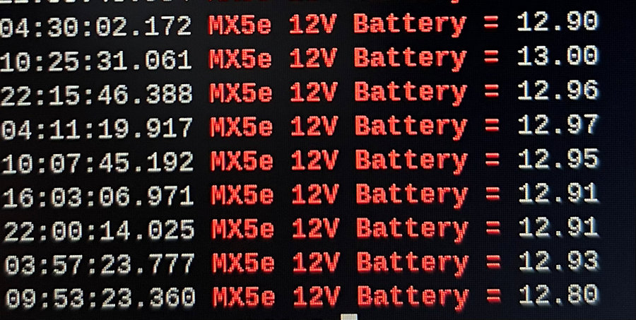
We use an algorithm to measure an the 12V battery voltage. We take 20 samples, sort them by value and then use the average of the middle 10 readings. This gives us an accurate and consistent battery voltage to 2 decimal places.
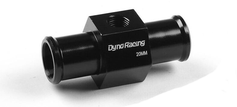
We are installing these inline temperature sensor housings to measure the inverter outlet temperature, the motor outlet temperature and the radiator outlet temperature.
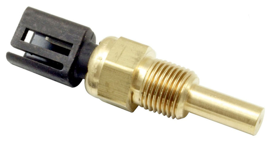
We are using these Lucas SNB1441 sensors with 1/8" × 27 NPTF thread. These are NTC (negative temperature coefficient) temperature-dependent resistors and are interfaced to the analogue pins on an Arduino processor. One side of the sensor is connected to ground and the other to the Arduino analogue input. A 1KΩ resistor from the analogue input pin to 3.3V is required.
Two digital outputs are used to select the speed and a single digital input is used to detect an error signal with our Tesla pump speed controller.
The DCU enables selection of the vehicle mode via three buttons, with audible acknowledgement.
The automatic driver profile selection mechanism is designed to simplify the user experience and minimise the driver interaction required before setting off. It also enables a personalised driving experience.
The DCU detects the driver and selects the correct driver profile automatically, prioritising the last one to drive. In the MX-5e, this is done using BLE tags. If two or more drivers and tags are seen, another driver profile can be selected by cycling through them using a 'change driver' button.
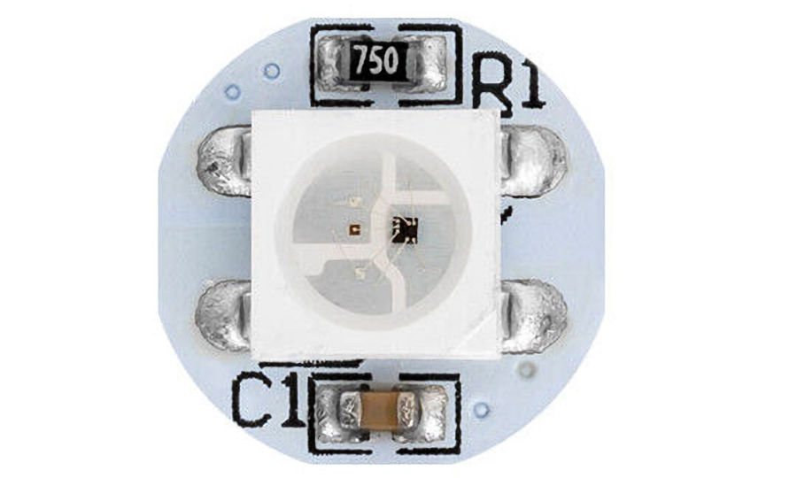
The DCU directly controls the ambient lighting in the cabin and it is personalised to each driver profile. The DCU communicates with a number of WS2812B 5050 RGB LEDs via a 5V signal and power supply.
The LEDs behind the driving profile and vehicle mode are also lit usign these LEDs, to enable them to be backlit at night and to change colour to show the selected option.
The DCU enables selection of the driving profile via four buttons, with audible acknowledgement. It remembers the last profile used by each driver.
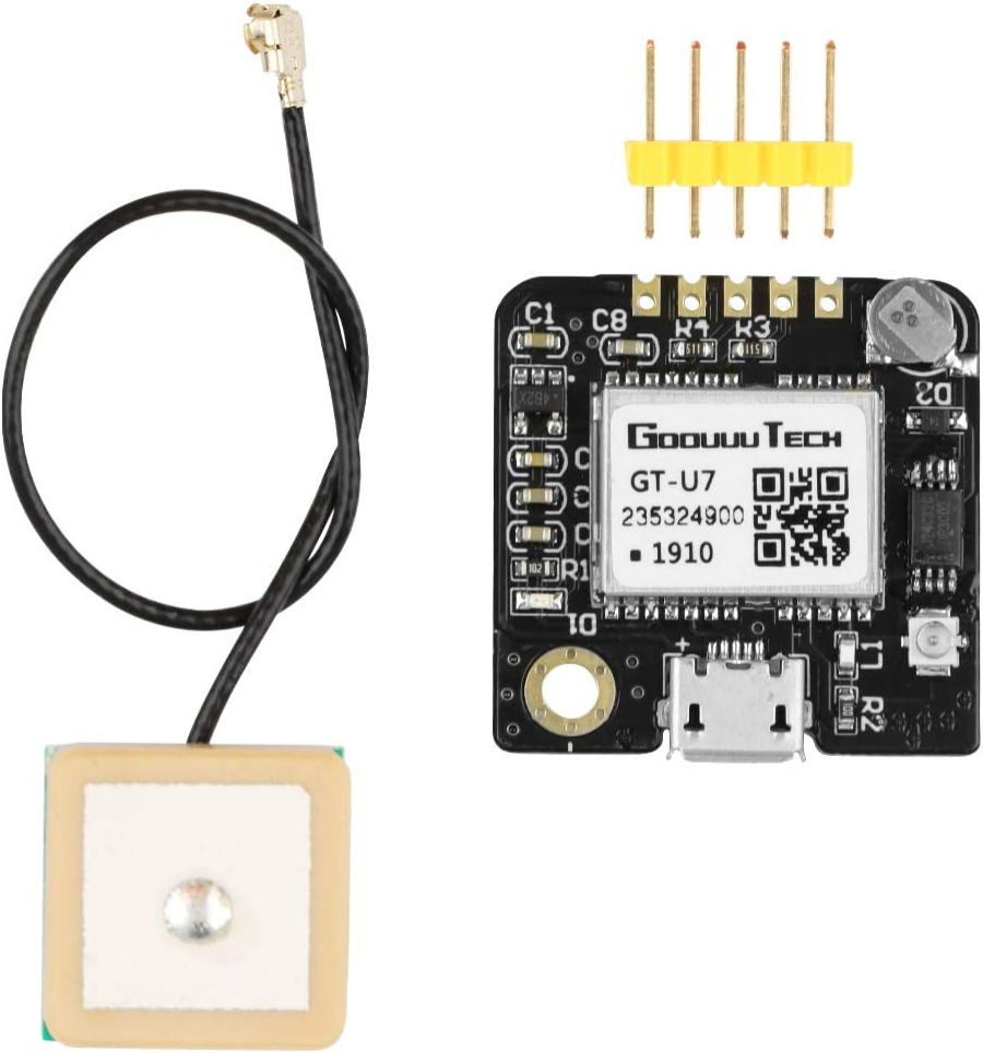
We have successfully interfaced a NEO-6M GPS module to ESP32 #1 via the Serial2 port. This provides real-time longitude, latitude, altitude, speed and an accurate time & date. There is an open-source library for the Arduino processor IDE.
As part of the DCU, the GPS module cannot be left permanently connected to the 12V battery because it uses about 45mA. For this reason, it is only powered when the ignition is on.
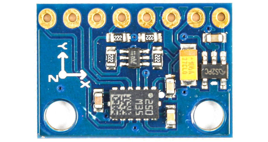
We are using the GY-511 module which includes a 3-axis accelerometer and a 3-axis magnetometer. This sensor can measure the linear acceleration at full scales of ±2 g / ±4 g / ±8 g / ±16 g and magnetic fields at full scales of ±1.3 / ±1.9 / ±2.5 / ±4.0 / ±4.7 / ±5.6 / ±8.1 Gauss. GY-511 compass module has 8 pins, but you need only 4 of them to interface with Arduino. This module communicates with Arduino processor using the I2C protocol, so we connect the SDA (I2C output) and SCK (I2C clock input) pins of the module to the I2C pins on the Arduino processor processor. There is an open-source library for the Arduino processor IDE.
The DCU will have the ability to play audio files and make multiple tones. These can be used for audible feedback on pressing buttons or switches. They can also be used to NOT DEFINED the driving experience.
To pick up data from the Tyre Pressure Monitoring System (TPMS) sensors in the wheels, we are using a CC1101 module interfaced to ESP32 #2 via an SPI interface.
Our development focus has shifted to the ESP32 as its very low power consumption allows it to be permanently connected to the 12V battery in 'deep sleep' mode and supports it all of the required features.
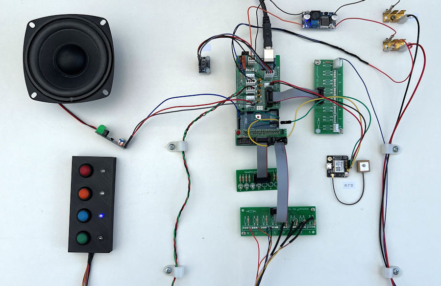
For the initial development and testing in the MX-5e, we were using an Arduino processor Mega 2560 Pro. The ATmega2560 has 256KB of flash memory for storing code (of which 8KB is used for the bootloader), 8KB of SRAM and 4KB of EEPROM (which can be read and written with the EEPROM library).
The DCU elements are built using modular components, linked via connectors and ribbon cables. Rob has used this approach with previous smart home and smart vehicles projects and it makes it very easy to develop and test the various components. They are also able to handle the harsh environment found in vehicles, particularly the vibration.
DCU2 needs to control 12V power to the Vehicle Control Unit (VCU) and provide a 12V signal to the dc-dc converter directly. It also needs to controls relays to the fans and pumps. We have designed a dedicated PCB with 'high side' switching for the following:
It also has a logic level converters for the 'DCU2 wait' signal (5.0V output to 3.3V input) and the serial communications between DCU1 and DCU2.
The OSSEV® philosophy is to open-source our designs and once we are happy our development and testing is complete, we will share our PCB designs and all the software we have developed for our DCU.