Open-Source Sports Electric Vehicle (OSSEV®)

In an EV there are a number of parts that require cooling:
There are few features to consider when designing the cooling system:
In our design we are monitoring the following temperatures:
In order to get accurate temperature readings, the pumps are always running when the EV is in use or charging, to ensure the water flows past the temperature sensors. The speed is controlled based on sensed temperatures. In our design we are using two pumps with a common radiator, which features dual fans. Dual fans ensure decvent airflow when the cooling system is being used and the EV is stationary.

A variable speed, electric water pump is required to pump water around the cooling system in an EV. We are using the pump from a Tesla EV because there are loads of them about, both new and second hand. They also meet our requirements very closely. The use of temperature sensors in the cooling system enables intelligent pump speed control, to reduce energy usage. The pump also features rotational speed monitoring, to ensure it is working as expected.
The pump has to be installed with the right orientation, such that air cannot get trapped inside it. This limits the possible orientations a little bit. The pump will not run if it detects there is no liquid present.
We are installing the pump on the 'cold side' of the radiator, to minimise its exposure to heat. Power to the pump is via the ignition switch. The Driver Control Unit (DCU) controls its speed and also monitors its rotational speed.

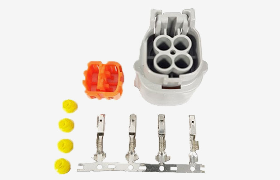
The pump requires a very specific 4-pin connector but, these are readily available at a reasonable price.

We could not find anything online that tells you how to put the connector together. The first thing to note is that the small round seals need to be put over the wires before you crimp the pins on. The connectors are crimped on and we also soldered them too, for extra reliability. The pins are L-shaped and needed to be inserted into the back of the connector with the right orientation and they then lock in place. We are not sure what the front orange clip does but this goes on last.
For our wiring we used 1mm2 wires for the +12V (red) and GND (black) and 0.25mm2 for the PWM control (pink) and pump speed sense (blue).

The pinout for the pump connector is documented in the pump specification.

The pinout for the pump connector is documented in the pump specification.

To control the pump speed, we have developed our own Tesla pump speed controller.

We are using three temperature sensors in the MX-5e cooling system for the motor to measure:
These are used by the Driver Control Unit (DCU) to determine the required pump speed and this is controlled using our Tesla pump speed controller.
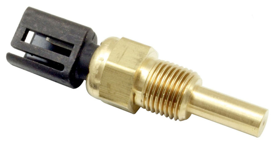
The temperature sensors are standard Lucas vehicle temperature sensors that change their resistance with temperature. To be able to measure the water temperature, the pump has to be running all the time the EV is in operation, if only at its lowest speed.
We are using these Lucas SNB1441 sensors with 1/8" × 27 NPTF thread. These are basically 2-pin thermistors and will be interfaced to the analogue pins on an Arduino processor.

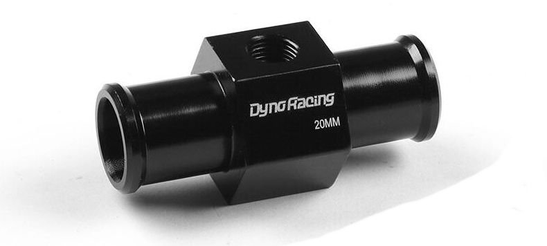
The temperature sensors sit in these in-line housings. They don't restrict the flow in much at all.
We have used 0.7mm² wiring for the sensors. The colour coding is:
The Driver Control Unit (DCU) has analogue input ports and these are used to measure the voltage across the sensor and hence its resistance. Our Driver Control Unit (DCU) has a 3.3V analogue input and a 1KΩ resistor is connected to both +3.3V and one side of the sensor. The other side of the sensor goes to ground. The junction point is connected to the analogue input. Typically, we take samples every 5 seconds when the ignition is enabled.
The temperature sensors are calibrated by measuring their resistance at room temperature and in boiling water. These two points can be plotted to give a simple linear equation that can be used to calculate temperature based on the resistance seen.
We are using silicon hoses for the cooling system. This is just some of them.